
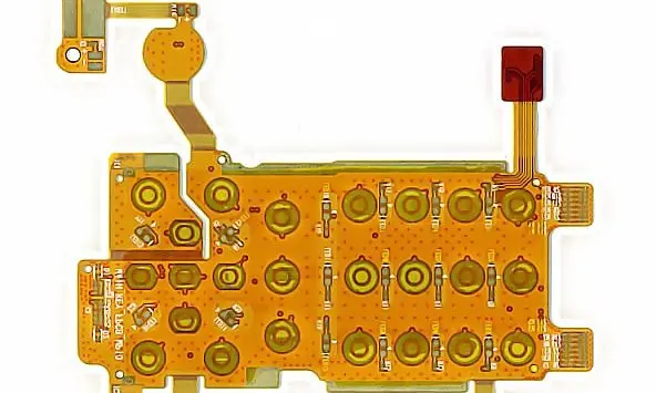
Preserve acoustic and mechanical interfaces
Locate microphone, receiver and control features from the housing datums that position their openings or actuators. Keep the flex route visible in the complete assembly model. The tolerance planning guide helps avoid using a long flexible outline as the only reference for a precisely located component.
Hearing-device interface review
| Interface | Define | Verify |
|---|---|---|
| Acoustic element | Position, orientation and opening | Alignment in the housing |
| Replaceable module | Connection and removal method | Controlled mating and load path |
| Sensitive signals | Routing and reference requirements | Complete assembled performance |
Choose a service boundary deliberately
Decide which subassemblies are replaceable and which connections are permanent. Detachable interfaces consume space and need accessible mating operations; permanent joints shift attention to assembly sequence and strain relief. Compare these choices using the connector selection guide.
For a battery compartment or removable module, identify user handling separately from factory assembly. State which motions the circuit experiences during replacement. Avoid relying on the flex or its solder joints to restrain an inserted module unless that load path has been explicitly designed and evaluated.
Review noise and handling in the assembled device
Describe sensitive analog paths, power loads and any radio interface so the electrical review can assess the whole route. Define suitable product-level checks with the design owner, including behavior after servicing and environmental exposure. A material datasheet does not establish acoustic performance, skin compatibility or approval of the finished device.
Before you release the design
- Include the housing features that locate acoustic elements.
- State replaceable versus permanent subassemblies.
- Map battery or module replacement motion.
- Define electrical and product acceptance with the design owner.
Watch points
- A serviceable module can still be difficult to replace if the connector latch becomes hidden during assembly.
Practical questions
Does a miniature circuit eliminate the need for reinforcement?
No. Small connectors and component areas still need appropriate support. Specify the local load and interface rather than assuming size makes it negligible.
Can this guide establish device approval?
No. The device owner must define applicable requirements, qualification and documentation. This guide helps organize the interconnect design and manufacturing inquiry.
Technical references
References support the material or design context. Check the exact grade, part number, document revision and project conditions before release.Updated 27 September 2026 · Technical content policy · Engineering guidance supports project review; the agreed drawing defines the build.