
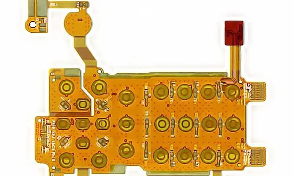
Specify the whole camera link
List the interface, lane or signal allocation, channel length, connector chain and required electrical targets. Use controlled-impedance planning to define trace and reference requirements. A laminate property or connector speed label alone cannot verify the assembled channel.
Keep connector pin assignments and transitions in the review. The Molex interface guide explicitly presents board-dependent simulated results, illustrating why connector data must be interpreted within its stated conditions rather than transferred directly to a complete camera assembly.
Machine-vision link review
| Area | Required input | Acceptance focus |
|---|---|---|
| Data channel | Interface, length and connectors | System-defined channel performance |
| Optical mount | Datums and load path | Stable camera location |
| Motion and environment | Route, lighting and power | Function under representative conditions |
Keep optics and flex loads separate
Show how the camera module is located and which structure takes cable or connector forces. Review the strain-relief route so a moving or tensioned ribbon does not disturb the optical mounting. Include access for focus, lens adjustment or camera replacement if these are product requirements.
Test with motion and neighboring electronics
For a moving inspection head, provide the actual movement envelope, mounts and contact risks. For a fixed camera, document installation bends and vibration conditions. Verify the channel in a representative assembly with the intended lighting, power and enclosure configuration. Record intermittent errors and image-function criteria using the camera-system owner’s acceptance procedure.
Before you release the design
- Document the entire link rather than the flex alone.
- Define optical mounting and cable-force restraint.
- Include illumination and neighboring power routes.
- Agree electrical and image-function test conditions.
Watch points
- An electrically continuous ribbon can still fail the camera link’s signal-quality or functional requirements.
Practical questions
Will shielding always solve image errors?
No. First identify the interference or channel issue. Reference paths, connectors, power integrity, grounding and the enclosure can all affect the result.
Can a high-speed connector rating be used as proof?
No. Review its stated configuration and test conditions, then verify the actual channel and application acceptance targets.
Technical references
References support the material or design context. Check the exact grade, part number, document revision and project conditions before release.Updated 27 September 2026 · Technical content policy · Engineering guidance supports project review; the agreed drawing defines the build.