
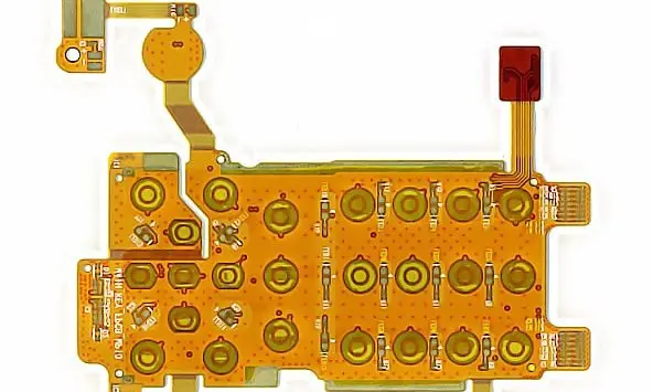
Map the sensing topology before the outline
Provide the cell or module arrangement, measurement nodes, sensor positions and connector assignment. Identify each route’s voltage and current conditions with the pack engineer. The power-routing guide helps keep sensing functions distinct from power-distribution decisions.
If spacing or insulation is safety-critical, the pack owner must supply the applicable system requirements and conditions. Do not infer them from the base film or coverlay name. Define exposed connection areas and their relationship to neighboring conductive structures in the installed assembly.
Battery sensing flex inputs
| Area | Provide | Review |
|---|---|---|
| Topology | Nodes, sensors and connector map | Correct function and identification |
| Connection | Joining method and local support | Qualified interface and load path |
| Installation | Pack tolerances and protection | Clearance and assembly access |
Choose connection and restraint methods together
Describe the intended joining method at cells, bus structures or sensor contacts and who qualifies it. Review strain relief so pack assembly, vibration or relative movement does not load the electrical joint unexpectedly. Include positional tolerances across the complete pack rather than one ideal cell.
State whether the flex is installed before or after neighboring hardware and how it is protected from tools and edges. The chosen route must remain inspectable where acceptance requires checking a joint or exposed conductor.
Verify the assembled pack interface
Define continuity, sensor function, insulation and environmental checks through the responsible pack team. Use representative mounts and joining processes in prototype evaluation. Track circuit revision, material and connection changes because they can affect the validity of previous evidence. No generic flex construction establishes battery-pack safety or qualification.
Before you release the design
- Separate sensing, sensor support and power functions.
- Supply pack-defined electrical and isolation requirements.
- Document joining process and qualification ownership.
- Review tolerances and access across the complete pack.
Watch points
- A sense circuit should not be assumed suitable for a power role because its outline reaches the same locations.
Practical questions
Can flex replace every wire in a battery pack?
Evaluate each function separately. Current, voltage, protection, movement, joining and service requirements determine whether a flex route is appropriate.
Who defines the insulation requirements?
The responsible pack or system engineer must provide the applicable requirements and conditions. They cannot be derived from this general application guide.
Technical references
References support the material or design context. Check the exact grade, part number, document revision and project conditions before release.Updated 27 September 2026 · Technical content policy · Engineering guidance supports project review; the agreed drawing defines the build.