
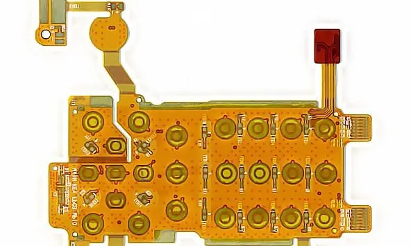
Specify the installed RF environment
Provide the enclosure, nearby conductors, battery, mounting adhesive and intended location relative to users or other objects. State the required RF performance through the antenna designer. The low-loss material guide helps identify frequency and construction details needed when comparing material data.
Treat the installed geometry as part of the antenna definition. Curvature, spacing and surrounding structures should be included in simulation or measurement as appropriate to the project. A flat fabrication drawing alone cannot describe the final electromagnetic environment.
Antenna fabrication brief
| Input | Define | Reason |
|---|---|---|
| RF objective | Band and designer-owned targets | Meaningful acceptance |
| Installed geometry | Shape, enclosure and nearby conductors | Representative electromagnetic environment |
| Feed and mounting | Interface and attachment stack | Controlled repeatability |
Control the feed and attachment interface
Identify the feed connection, ground arrangement and cable or connector route. Use impedance planning where the feed requires a controlled transmission path. Dimension mounting and locating features from the RF-relevant geometry so assembly variation can be assessed.
If adhesive attaches the antenna to an enclosure, specify the material and placement rather than leaving a generic tape note. Include the installation procedure and allowable positioning variation in the release package.
Preserve representative measurement conditions
Agree who tunes and verifies the antenna and which assembled states are tested. Record enclosure revision, nearby hardware, feed arrangement and mounting conditions with results. A material substitution or relocation can require renewed RF review even if the circuit still fits mechanically. This guide does not promise frequency coverage, efficiency or regulatory compliance for an unspecified design.
Before you release the design
- Provide the installed product environment.
- Specify material data at relevant frequencies.
- Control feed geometry and mounting materials.
- Tie tuning and measurement records to assembly revision.
Watch points
- Copying an antenna outline without its substrate, feed and surrounding geometry does not reproduce its performance.
Practical questions
Can a low-loss laminate guarantee antenna performance?
No. Performance depends on the complete antenna, feed, installation and environment. Use material data within the RF design and verification process.
Does bending only change packaging?
Do not assume so. The installed shape is part of the RF geometry and should be considered by the antenna designer.
Technical references
References support the material or design context. Check the exact grade, part number, document revision and project conditions before release.Updated 27 September 2026 · Technical content policy · Engineering guidance supports project review; the agreed drawing defines the build.