
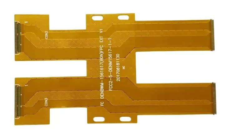
Separate material from architecture
Polyimide may be the base film, a coverlay film, or part of a reinforced region. Those uses need different drawing information. A flexible tail with two copper layers is a different engineering problem from a component island supported by a stiffener, even when both contain polyimide. Map the electrical connections and mechanical regions before selecting a laminate. The flexible circuit overview explains the architecture choices; the materials guide separates the constituent materials.
Translate a broad polyimide request into engineering inputs
| Question | Record | Decision supported |
|---|---|---|
| What moves? | Assembly folds and service motion separately | Bending span and qualification plan |
| What connects? | Connector drawing and contact orientation | Tail thickness and reinforcement |
| What carries signals? | Nets, reference strategy and electrical limits | Copper count and dielectric geometry |
| What gets hot? | Process profile and service exposure | Full material-system review |
Build the decision around the product
Describe where the circuit sits during assembly, how it moves in service, and what supports it. Include enclosure clearances, connector locations, expected handling, temperature exposure, and electrical requirements. Then assign a local construction to each region. A connection pad can need reinforcement while the adjacent routing span needs freedom to bend. Carry both requirements into the same drawing so the reinforcement does not consume the intended bending length.
Qnity describes Pyralux AP as an adhesiveless all-polyimide copper-clad laminate. That is one product construction, not a definition covering every polyimide circuit. Adhesive, coverlay, surface finish, shielding, and assembly materials still need separate decisions. A film datasheet cannot substitute for the assembled board specification.
Turn a material request into a reviewable package
Replace a note such as ‘polyimide, flexible’ with a region drawing, ordered stackup, proposed material grades, copper description, and critical finished dimensions. State whether substitutions are acceptable and which properties require a new review. Compare candidate builds against the same duty and acceptance plan. Use the stackup drawing guide to make layer order visible, then include unresolved questions in the quote brief.
Qualification should exercise the proposed construction in its intended installation. A flat electrical test and a supplier material result answer different questions. Define how motion, temperature, moisture, and connector operation interact in your product; select the checks that resolve those risks without treating an unrelated material claim as a service-life guarantee.
Before you release the design
- Mark flexible, reinforced, and component regions on one outline.
- Identify all film, adhesive, copper, and protective layers.
- Attach the connector part number and drawing revision.
- Separate required properties from preferred brands.
- Document what the prototype must demonstrate.
Watch points
- A polyimide name alone is not a laminate order code or bend-life requirement.
- Do not apply a film temperature figure to solder joints, adhesives, connectors, or the finished product.
Practical questions
Is every polyimide PCB flexible?
No. Determine the actual construction and thickness distribution. A material description does not establish the mechanical behavior of the assembled board.
Can a supplier replace one polyimide grade with another?
Only through an agreed substitution review. Compare construction, measured-property context, processing, availability, and the qualification evidence required for your product.
Technical references
References support the material or design context. Check the exact grade, part number, document revision and project conditions before release.Updated 27 September 2026 · Technical content policy · Engineering guidance supports project review; the agreed drawing defines the build.