
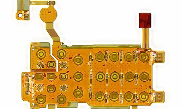
Define the camera interface end to end
Provide the interface specification, signal assignment, routing length, connectors and required channel targets. Review differential-pair routing within the accepted stack, including transitions and references. Do not use nominal material properties as proof that the assembled link meets the camera system’s requirements.
Where a connector guide supplies simulated performance, preserve its circuit assignment and board assumptions. The cited Molex guide is an example of why channel evidence must be read with its conditions. Request validation relevant to the actual module and host connection.
Camera-module engineering inputs
| Interface | Specify | Check |
|---|---|---|
| Electrical link | Stack, references and connector chain | Channel requirements |
| Mechanical location | Module datums and support | Alignment after flex installation |
| Assembly | Latch access and forming sequence | Controlled loads and clearances |
Keep mounting and connector loads controlled
Show the camera locating features and the supported region beneath any mounted connector. The local reinforcement guide helps frame this support requirement. Include the mating sequence and access to the latch, because a connector can be electrically correct but inaccessible after the camera is installed.
Verify optical position after routing
Use representative mounts and enclosure parts to inspect the installed route and camera alignment. Check that forming the ribbon or closing the housing does not pull the module away from its locating surfaces. Distinguish fixed packaging from autofocus, stabilization or other moving subassemblies; if the circuit moves, define that motion explicitly and add a representative endurance evaluation.
Before you release the design
- Provide the full camera-to-host connection definition.
- Identify the structure that locates the camera.
- Check connector support and latch access.
- Declare any module motion separately from installation bending.
Watch points
- A stiff ribbon or inaccessible connector can disturb an otherwise accurate camera mount during final assembly.
Practical questions
Can a flex be selected from the camera interface name alone?
No. Include the actual channel length, connector configuration, pin assignment, stack and validation targets.
Does every camera module need dynamic flex?
No. A fixed mounted camera has a different duty from a circuit that follows stabilization or another mechanism. Describe what actually moves.
Technical references
References support the material or design context. Check the exact grade, part number, document revision and project conditions before release.Updated 27 September 2026 · Technical content policy · Engineering guidance supports project review; the agreed drawing defines the build.