
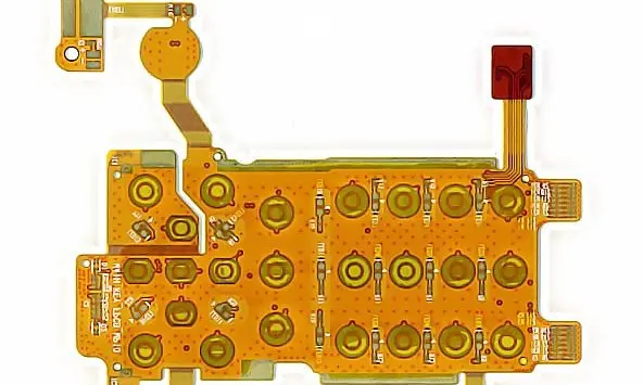
Locate the sensor from functional datums
Define the sensing face, axis or contact point in the housing coordinate system. State which component or circuit feature establishes that location. The tolerance guide helps distinguish a critical sensor-to-housing relationship from an outline dimension that has little effect on function.
Industrial-sensor specification
| Constraint | Provide | Check |
|---|---|---|
| Sensing alignment | Functional datum and tolerance | Position after closure |
| Narrow enclosure | Insertion route and tools | Assembly without damaging the flex |
| External connection | Cable load and environment | Supported protected termination |
Review insertion and termination together
Provide the assembly sequence through tubes, slots or cavities, including the tools used to position the electronics. A mechanical model should include connector and component height, temporary bends and access for fastening or joining.
Identify the boundary between the sensor electronics and external cabling. Define vibration, cable loads and protection against the actual environment as project inputs. If encapsulation or coating is proposed, discuss material compatibility, strain transfer, inspectability and repair with the responsible process engineer rather than treating it as a universal fix.
Measure after the final assembly step
A sensing element can move when the enclosure is closed or a protective material is applied. Define dimensional and functional checks at the stage that represents the delivered product. Keep the local stack and support construction controlled so that a later material or adhesive change receives a review of its impact on alignment and sensing behavior.
Before you release the design
- Dimension the sensing element from its functional interface.
- Model insertion as well as the installed state.
- Define encapsulation or coating responsibilities if used.
- Verify position and function after final assembly.
Watch points
- A correct bare-board outline does not guarantee sensor alignment after fastening, encapsulation or case closure.
Practical questions
Can flex replace a rigid sensor board?
It may help packaging, but preserve the required sensing position and component support. Compare the complete installed assemblies, not only their board shapes.
Should the entire flex be encapsulated?
That depends on protection, movement, repair and material compatibility. Define the intended process and assess its effect on the actual assembly.
Technical references
References support the material or design context. Check the exact grade, part number, document revision and project conditions before release.Updated 27 September 2026 · Technical content policy · Engineering guidance supports project review; the agreed drawing defines the build.