
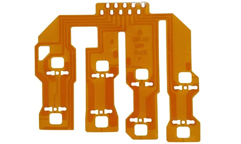
Give the second layer a defined function
Use the extra layer to solve a named problem: crossing nets, distributing power, providing a reference, or connecting devices on opposite faces. Compare the result with a two-layer stackup. Avoid adding a continuous copper reference without considering how it changes the region that must bend.
Define each feature of a two-layer request
| Feature | Information required | Review question |
|---|---|---|
| Layer function | Signals, returns and power | Where is the reference actually needed? |
| Vias | Drill data and connectivity | Are transitions outside moving regions? |
| Contacts | Exposed face and local stack | Does the tail match the connector? |
Review plated connections and motion together
Identify each plated hole and distinguish it from mechanical holes and slots. Mark moving areas before finalizing layer changes. A via that is electrically convenient may be mechanically awkward near a bend or stiffener edge. The via planning guide helps frame this joint electrical and mechanical review.
Specify base copper and finished copper expectations unambiguously; fabrication processes may add copper locally or more broadly. Request the proposed construction rather than estimating flex thickness from a laminate label alone. Contact-tail and impedance requirements should use the accepted finished stack.
Inspect both faces as functional surfaces
Provide coverlay openings for each face and state the viewing convention on drawings. Show component, connector and reinforcement orientation with an installed view. Agree how electrical test covers interlayer connections and how critical tail thickness or registration will be checked. If both faces are assembled, include support and access for each assembly step.
Before you release the design
- Assign a purpose to each copper layer.
- Differentiate plated and nonplated drill features.
- Check coverlay and stiffener drawings from both faces.
- Include electrical-test and critical-dimension requirements.
Watch points
- Confusing starting foil thickness with finished copper can invalidate thickness and impedance assumptions.
Practical questions
Does two-layer flex always need vias?
Only the required connectivity determines that. State whether the layers connect and provide the actual interconnect data; do not let the construction name substitute for a netlist.
Is a solid second layer the best reference?
Evaluate the electrical return requirement, local thickness and motion together. Any alternative copper pattern needs electrical review and application-specific verification.
Technical references
References support the material or design context. Check the exact grade, part number, document revision and project conditions before release.Updated 27 September 2026 · Technical content policy · Engineering guidance supports project review; the agreed drawing defines the build.