
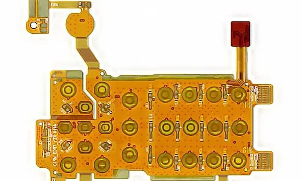
Separate measurement and user-interface paths
Identify the function of each connection: measurement signals, display, communications, power or controls. Define the relevant electrical requirements with the meter designer. The power-distribution guide helps distinguish a signal interconnect from a conductor expected to deliver meaningful current.
Where electrical isolation or spacing is product-critical, provide the system owner’s required values and applicable conditions. This guide supplies no universal safety spacing; insulation and conductor placement must be reviewed within the complete meter design and its acceptance requirements.
Smart-meter inquiry inputs
| Function | Define | Verify |
|---|---|---|
| Measurement and power | Circuit role and electrical limits | Product-defined electrical acceptance |
| Housing assembly | Display and connector route | Closure without loading contacts |
| Long service interval | Environment and replacement policy | Controlled construction and records |
Control enclosure assembly and long-term interfaces
Show the display and module locations, connector orientation and case-closing sequence. Review folding and installation so closure does not preload a connector or trap a tail. State temperature, humidity and mechanical conditions as actual project inputs rather than a broad outdoor or indoor label.
Plan controlled service and replacement
Decide whether the meter is serviced as a complete unit or by subassembly. Define any seal-sensitive or restricted-access interfaces with the product owner. A prototype evaluation should include closure, expected environmental testing and the agreed electrical or functional checks. Preserve construction and lot records needed to relate a later field investigation to the original build.
Before you release the design
- Identify measurement, power and display connections separately.
- Provide owner-defined isolation requirements where applicable.
- Model the final case-closing sequence.
- Specify service boundary and required build records.
Watch points
- A material described as insulating does not establish the complete product’s isolation or long-term environmental performance.
Practical questions
Can one flex carry display signals and power?
It may, but define current, voltage, references, isolation and interface requirements for each function. Review the complete local geometry and construction.
What matters when no field repair is planned?
Clarify the complete-unit replacement policy and required verification evidence. Inaccessibility makes controlled assembly and traceable acceptance particularly useful.
Technical references
References support the material or design context. Check the exact grade, part number, document revision and project conditions before release.Updated 27 September 2026 · Technical content policy · Engineering guidance supports project review; the agreed drawing defines the build.