
Start with the process that needs support
A bare-circuit panel and an assembly panel may have different priorities. Identify placement-machine support, soldering fixtures, inspection access and the point at which each circuit becomes free. The assembly plan should be considered before a dense nesting arrangement is accepted.
Panel decisions across the workflow
| Need | Define | Check |
|---|---|---|
| Fabrication | Orientation and process margins | Critical features remain reproducible |
| Assembly | Support, fiducials and clearance | Equipment and fixture access |
| Separation | Method and delivered condition | No unintended loading of the circuit |
Preserve orientation and critical geometry
Label circuit orientation, reference features, tooling areas and any material-direction requirement. Review copper direction where it is part of the specified construction. Rotating a part to fill an empty space should not silently change an approved orientation requirement.
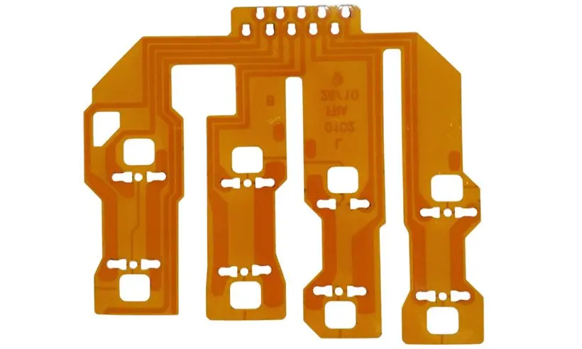
Check that long narrow branches and contact tails remain protected. A repeated layout may leave a fragile feature unsupported during transport or after neighboring parts are removed. Define what can touch temporary supports and what must remain clear of adhesive, tooling or clamp pressure.
Include separation in the drawing review
Ask how circuits leave the panel, who performs that step and which features remain on the delivered part. Review clearance for removal tools and the load path during separation. If assembled units are delivered, account for component access and height. Evaluate cost using acceptable finished units per panel, including handling effort and losses, rather than area utilization alone.
Before you release the design
- State whether delivery is in panels or separated units.
- Review the proposed panel with assembly requirements.
- Mark protected contacts, branches and bend areas.
- Include separation method and remaining outline features.
Watch points
- Maximizing circuits per sheet can increase total cost if the resulting panel is difficult to assemble or separate.
Practical questions
Should the designer provide a finished panel layout?
Provide constraints and any required panel drawing. Let the manufacturing and assembly review resolve process-specific details before the layout is released.
Can different circuit revisions share a panel?
Only with explicit identification, traceability and acceptance arrangements. Mixing revisions can create handling and test errors that outweigh apparent material savings.
Technical references
References support the material or design context. Check the exact grade, part number, document revision and project conditions before release.Updated 27 September 2026 · Technical content policy · Engineering guidance supports project review; the agreed drawing defines the build.