
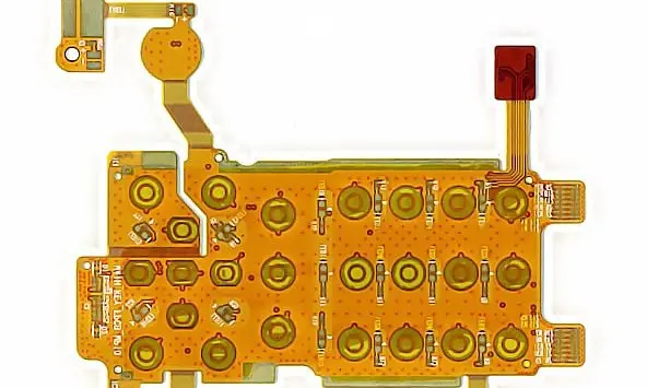
Read the display and connector drawings together
State whether the connection is detachable or uses a specified permanent joining process. For an FPC connector, verify contact pitch, insertion geometry, thickness and retention features against the exact drawing. The contact-finger guide organizes these checks without imposing a universal tail geometry.
Do not assume a display-supplied tail drawing can be transferred unchanged to a different connector. Even matching pitch can leave contact orientation, thickness or retention incompatible. Keep drawing revision and part number in the released package.
Display interconnect checklist
| Constraint | Define | Verify |
|---|---|---|
| Terminal compatibility | Part drawing, contact face and thickness | Correct mating and retention |
| Assembly access | Insertion and latch sequence | Tool and finger clearance |
| Installed route | Bends, supports and neighbors | No pinching or interface loading |
Reserve space for insertion and closure
Use installation planning to show how the tail is inserted, how the latch is operated and how the display is finally located. The space required during assembly may exceed the installed ribbon envelope. Protect the terminal from adhesive contamination and unintended bending during those steps.
Review the complete electrical and thermal context
List data, control and power functions with their applicable requirements. Check routing and references within the actual stack, particularly at connector transitions. Include neighboring heat sources and the enclosure conditions supplied by the product engineer. Prototype evaluation should combine display operation with inspection of the installed route, latch state and local support after closure.
Before you release the design
- Reference the exact display and connector drawings.
- Mark contact face and insertion direction explicitly.
- Include temporary assembly clearance in the model.
- Verify display function after enclosure closure.
Watch points
- A terminal with the right pitch can still have the wrong contact side, local thickness or retention geometry.
Practical questions
Is a common nominal tail thickness enough?
No. Use the connector’s specified tolerance and construction requirements, including reinforcement and contact geometry where applicable.
Can permanent bonding be treated like a connector?
No. Specify the joining process, equipment and acceptance requirements with the responsible manufacturer. It has a different assembly and repair boundary.
Technical references
References support the material or design context. Check the exact grade, part number, document revision and project conditions before release.Updated 27 September 2026 · Technical content policy · Engineering guidance supports project review; the agreed drawing defines the build.